13 March 2015
Yeager airport – a massive, damaging fill slope landslide
Posted by Dave Petley
Yeager Airport
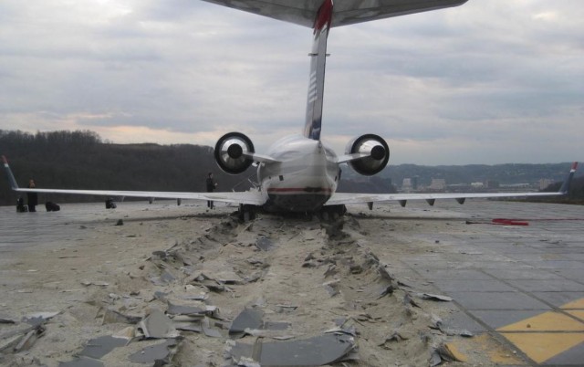
Yeager Airport is located about 5 km east of downtown Charleston in West Virginia, USA. The airport is located on top of a hill, with steep slopes on several sides, including at the end of the main runway. In 2005 a project was initiated to increase safety at Yeager Airport by creating an over-run area at the end of the runway, including the installation of an EMAS, which is a concrete surface that is designed to bring aircraft to safe stop. In 2010 this successfully arrested an over-running regional jet:
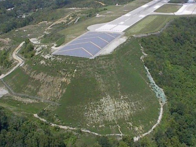
The construction of the EMAS required that a new, large fill slope was built, retained by a reinforced slope. There is a very detailed and interesting presentation about the design and construction of the slope (NB this is a PDF); at the time this was apparently the largest reinforced slope in the United States (I’m not sure if this is still the case). This images, from the presentation, shows the completed structure at the end of the runway at Yeager Airport:
.
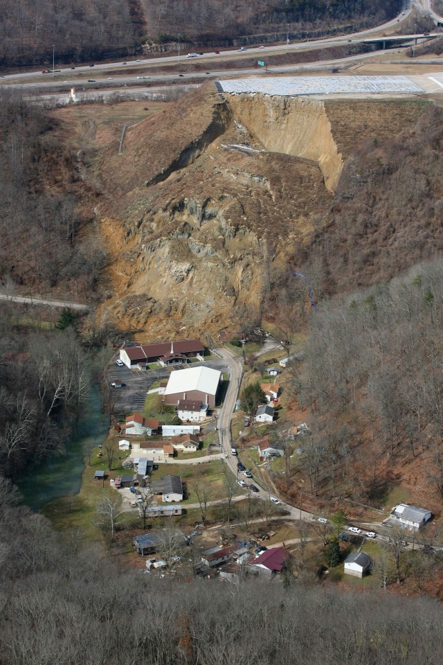
In Wednesday the Charleston Daily Mail reported that six residents had been moved out of their houses below the slope as movement of the slope had been detected in the EMAS. Yesterday this quickly developed into a very large-scale landslide. This image is from a gallery that is in a Charleston Daily Mail report from yesterday:
.
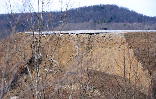
This is a massive, very deep-seated and rather complex failure. The scale is somewhat impressive. The failure is surprising in so much as the conditions appear to be dry, a fact that is supported by this image of the rear scarp, although as the comment below notes, there has been significant rainfall and snowmelt in recent weeks:
.
The slope reinforcement is clear to see in the image – the failure appears to have sliced through it. The images gives few indications as to what has gone wrong – whether this is a design failure or whether something happened at the toe of the slope to change the system. I do wonder if the rock below the reinforced slope has failed though – this might explain the interesting geometry of the collapse. Either way, this is going to be very expensive, and it will affect both the operations at Yeger Airport and the local residents for some time to come.


 Dave Petley is the Vice-Chancellor of the University of Hull in the United Kingdom. His blog provides commentary and analysis of landslide events occurring worldwide, including the landslides themselves, latest research, and conferences and meetings.
There are several videos of the landslide moving. Here is one: http://www.wdbj7.com/news/local/web-extra-raw-video-of-landslide-in-west-virginia/31767672
I’m a resident of Charleston. There’s actually been significant rainfall and snow over the past couple of weeks, causing floods, rock falls, mudslides, road erosion and even a bridge collapse all over the state. Even though the scarp looks dry, I would imagine the slip plane underneath everything is saturated.
Notice in the photos in the presentation you linked, how far back the reinforcement was placed, and then compare that to the depth of the shear plane of the slide. It looks like the ground sheared where the reinforcement ended, and the reinforced soil as a whole is sliding down the hillside. Yes the reinforcement is visible in the top layers, but not farther down, and it is at the base that the initial failure occurred, since this looks to be a rotational slide (http://bit.ly/19gySpU)
This is interesting because it was a reinforced fill embankment. Material appears to have been used for the entire fill height as seen in the last photo in the main article (with jet about to land).
This is a good clear shot of the scarp, and under zoom, it looks like they used some sort of reinforcing fabric, instead of a Tensar Geogrid equivalent. It looks as if there is some sort of grid backing to the fabric. Big sections appear to have literally pulled free the fill as it fell away. Non-fabric, open latticework products are much more resistant pull-out failure in granular fills.
PS: I agree that a founding bedrock failure is most likely the “smoking gun” in this case
This is the product used:
http://www.tencate.com/amer/Images/TDS_MG20XT_tcm29-17021.pdf
Google earth has a nice set of photos in street view showing the road at the toe before the event. There appears to be a block wall along part of this suggesting potential instability in the slope prior to the fill being placed. The embankment below appears quite soft, with power poles leaning down the hill. There is one area of bedrock exposure showing flat lying sedimentary rock. This appears to include a competent pale sandstone over a greyish finer grained rock (Shale/siltstone?). The orientation of bedding seems to be ok, though from the images it may be dipping slightly downslope. While a bedrock failure seems possible I would have expected some incremental movement in the lead up that should have been detected. Was this the case?
Where is the drain tile?
This site appears as a case study in the TenCate Product brochure which gives some of the technical details of the materials used, dimensions and site conditions. This site is about halfway through the brochure.
(see http://www.tencate.com/amer/Images/Reinforced%20Soil%20Case%20Studies_tcm29-19401.pdf )
Having designed similar structures (albeit much smaller) bearing capacity failure when they re constructed on a slope will often govern design, so it is typical to micropile at least the toe of the reinforced slope to provide some degree of protection. Also, I typically use a biaxial grid so that if part of the foundation does go, the surrounding wall can provide some degree of support. The XT geogrid used in the slope above is a uniaxial geogrid, which would account somewhat for the failure through the reinforced zone as the geogrid has low lateral strength.