21 December 2016
The Folkestone Warren landslide toe weight structure
Posted by Dave Petley
The Folkestone Warren landslide toe weight structure
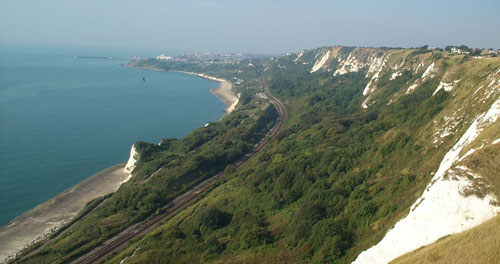
On the South Coast of England the railway line between Dover (the main ferry port for travel to Europe) and London crosses a very large landslide at Folkestone Warren in Kent. This is a large (3 km wide), deep-seated (the shear surface extends about 40 m below sea level) rotational landslide. The track crosses the entire width of the landslide, located on displaced blocks, as this BGS image shows:

The Folkestone Warren landslide, image from the BGS taken in 2002
.
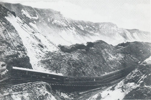
Unsurprisingly this railway line has a very long history of being disrupted by the landslide. The most famous incident occurred on 19 December 1915, when 1.5 million cubic metres of chalk slipped, causing enormous damage to the line. A train was caught in the landslide, but fortunately without any loss of life:

The 1915 landslide on Folkestone Warren, from British Railways, Southern Division via the BGS)
.
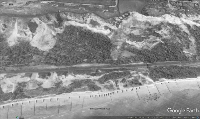
The line was closed until 1919. The slope remained active thereafter – this Google Earth image from 1940 gives a good impression of the magnitude of the problems that British Railways faced at that time:-

Google Earth image of the Folkestone Warren landslide from 1940
.
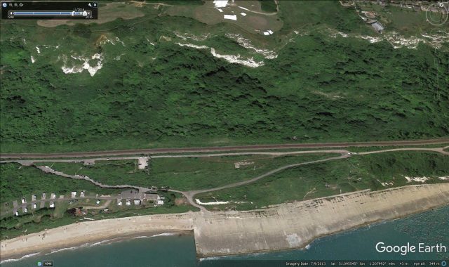
In 1948 an enormous toe weight structure, designed to add mass to the toe of the landslide to prevent further rotational failures, was constructed. This was extended between 1951 and 1952. There is a very nice article (N.B. this is a PDF), published in the Railway Magazine, on the Southern Railway E-mail Group (SREmG) site describing these works, and the associated drainage tunnels. This vast, and effective, toe weight can be seen in the modern Google Earth images as a platform built at the toe of the landslide:-

Google Earth image of the Folketsone Warren toe weight structure
.
The effectiveness of these and the associated landslide management measures is clear from the above image – the slide is much less active now than it has been in the past. But nonetheless this remains a deeply challenging section of railway line for Network Rail to maintain.


 Dave Petley is the Vice-Chancellor of the University of Hull in the United Kingdom. His blog provides commentary and analysis of landslide events occurring worldwide, including the landslides themselves, latest research, and conferences and meetings.
I wasn’t aware the Google Earth was available in 1940 to take the picture where you cite it 2x.
Google Earth has amassed a significant amount of imagery dating back as far as the 1940’s from historical sources. You might note the watermark in the 1940 image.
Fascinating!
I had always thought the drainage tunnels were to help keep the tunnels and track dry and the apron was to protect the line from tidal surges etc. I now understand they are to help stop any further land-slips. I will view the drainage adits and apron/sea wall from a different perspective next time I am down there.